

Technical How-To Guide For M&E Contractors and Data Center Build Teams
In modern data centers, floor cutouts are not minor installation details. They directly influence airflow efficiency, static pressure balance, and ultimately Power Usage Effectiveness (PUE). Poorly engineered openings increase bypass airflow, reduce cooling predictability, and raise fan energy consumption.
As a professional HUIYA raised access floor manufacture partner, understanding how to calculate, position, and execute cutouts under high-density environments is essential. This guide breaks down the engineering workflow step by step.
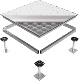
Figure 1. Standard raised access floor panel configuration used in data center environments (click image to view product details).
Step 1 – Calculate Required Airflow per Rack
Start with IT load. Assume one rack operates at 12 kW.
Convert power to heat load:
12 kW × 3,412 BTU/h = 40,944 BTU/h
Using standard airflow equation:
CFM = BTU/h ÷ (1.08 × ΔT)
Assume supply-return ΔT = 18°F.
CFM = 40,944 ÷ (1.08 × 18) = 2,104 CFM
If one perforated tile delivers 800 CFM at design static pressure (0.1 in.w.g), the rack requires:
2,104 ÷ 800 = 2.63 → Round up to 3 airflow openings
This airflow requirement defines total effective cutout area.
Step 2 – Optimize Placement Under Hot Aisle Containment
When deploying 热通道封闭 systems, follow guidance from Hot Aisle Containment airflow management guidelines. Position cutouts strictly within cold aisle zones.
Do not place cable cutouts behind racks inside hot aisles. That practice induces short-circuit airflow and raises inlet temperatures.
Figure 2. Cold aisle vs hot aisle airflow organization comparison.
Use blanking panels and brush grommets to control leakage. A 100 mm × 400 mm unsealed cable opening can leak approximately 150–200 CFM at 0.1 in.w.g.
Step 3 – Engineer Structural Integrity of Cut Panels
Cutouts reduce panel load capacity. A standard 600 mm steel cementitious panel rated at 4,500 N concentrated load may lose 15–25% capacity when a 150 mm cable opening is introduced.
Calculate residual load:
4,500 N × 0.8 = 3,600 N remaining capacity (conservative)
If rack wheel load equals 3,200 N, safety margin shrinks significantly.
Install reinforcement frames or use factory-prefabricated cut panels supplied by certified raised floor manufacture vendors such as HUIYA INC.
Step 4 – Evaluate PUE Impact and Compliance Requirements
Field measurements from airflow optimization projects show that sealing unmanaged cutouts can improve PUE from 1.65 to 1.58 in medium-density halls (source: industry airflow case benchmarking).
Reduced bypass airflow lowers CRAC fan speed by 5–10%, translating into measurable energy savings.
Align final cutout design with redundancy and resilience criteria referenced in Uptime Institute Tier standard requirements.
Compliance documentation should record cutout locations, airflow calculations, and reinforcement details as part of commissioning packages.
Common Design Errors
| Error | Engineering Impact |
|---|---|
| Random cable openings | Uncontrolled airflow leakage |
| Oversized perforated tiles | Pressure imbalance |
| No structural reinforcement | Panel deflection risk |
| Hot aisle cutouts | Air recirculation |
| No commissioning test | Unverified PUE loss |
Installation Reference
Technical Documentation
Download the Data Center Floor Cutout Specification Manual (PDF) for dimensional tolerances, reinforcement details, airflow coefficient charts, and compliance documentation templates.
Floor cutouts are measurable engineering variables. When calculated correctly, aligned with airflow containment strategy, and structurally reinforced, they become controlled airflow devices rather than energy liabilities.